Makerfront Rebuild Part 2: Printed Parts?

Makerfront’s press releases for the i3PRO boasted: no printed parts! And in fact the extruder and z-axis carriages, commonly made from printed parts, were made of steel plates assembled with captive t-nut joints, just like the rest of the frame.
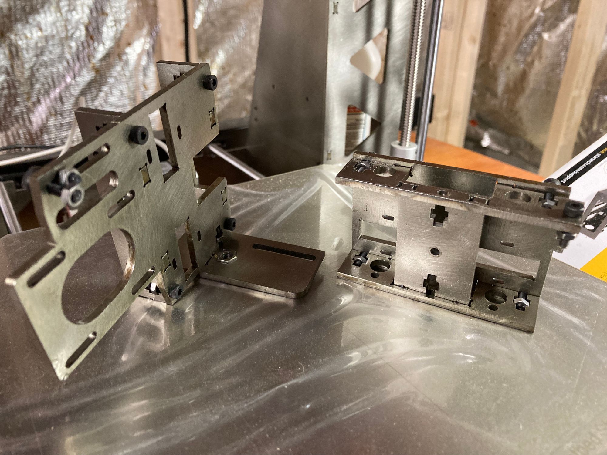
I appreciate the purity of design that went in to making these carriages from the same construction as the rest of the printer. I can see the line of thought which goes, it’s a steel printer, so it should all be steel. But as much as I can respect that opinion, I don't share it. So with my apologies to Makerfront, I rebuilt mine with 3D printed parts.
First, I dislike the insinsuation that 3D printed parts are inferior. If 3D printed parts are no good, why would I want a 3D printer in the first place? It certainly seems like a distasteful position for the maker of 3D printers. Or at least poor marketing. How much mileage has Josef Pruša made off of the fact that Prusa printers print Prusa printer parts? That’s not a gimmick (at least, not just a gimmick) it’s a testament to the fact that these machines are productive and capable of making real parts.
More importantly, those steel carriages are heavy. The weight and strength of steel makes it a great choice for the frame. But the extruder carriage at least should be as light as possible. The inertia of the carriage is the primary reason that printers can’t print faster. That's why Bowden tube extruders exist, and why extruder makers shave grams off of their products and get away with adding zeroes to their prices.
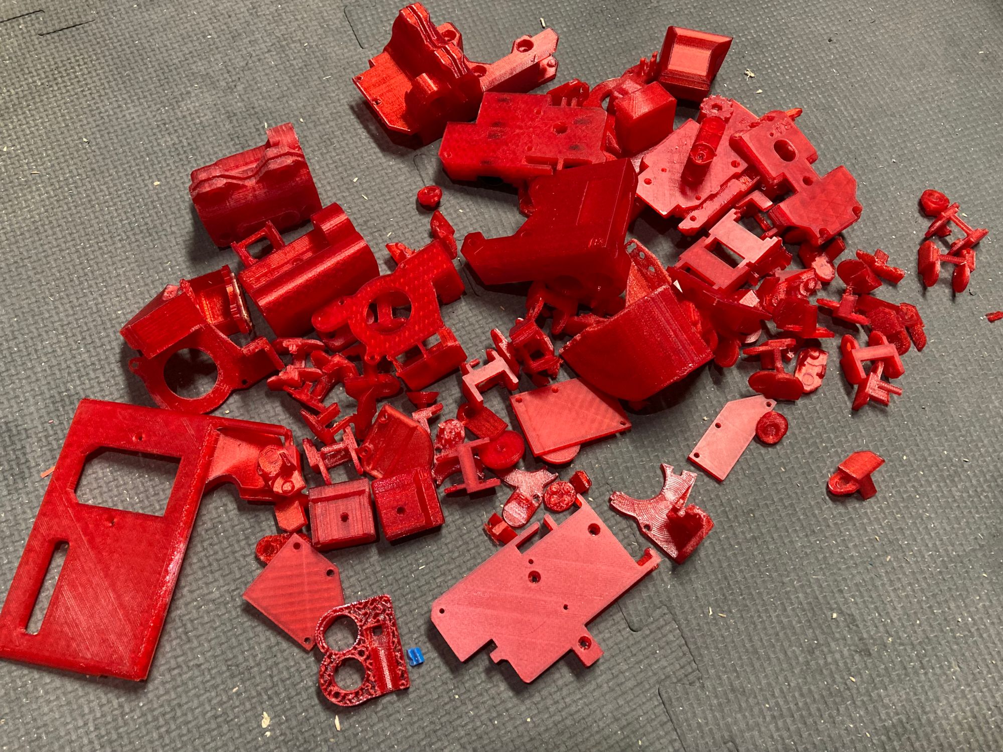
I tried (and often failed) not to reinvent any wheels here; these carriages are essentially what you would find on a Prusa Mk3 or Mk2. I started with the files for those from Prusa and modified as necessary in Fusion 360, then printed in Amazon Basics Translucent Red PETG (which I suspect is Overture filament rebranded as Amazon).
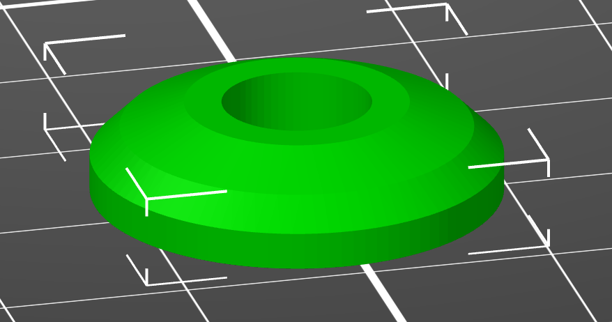
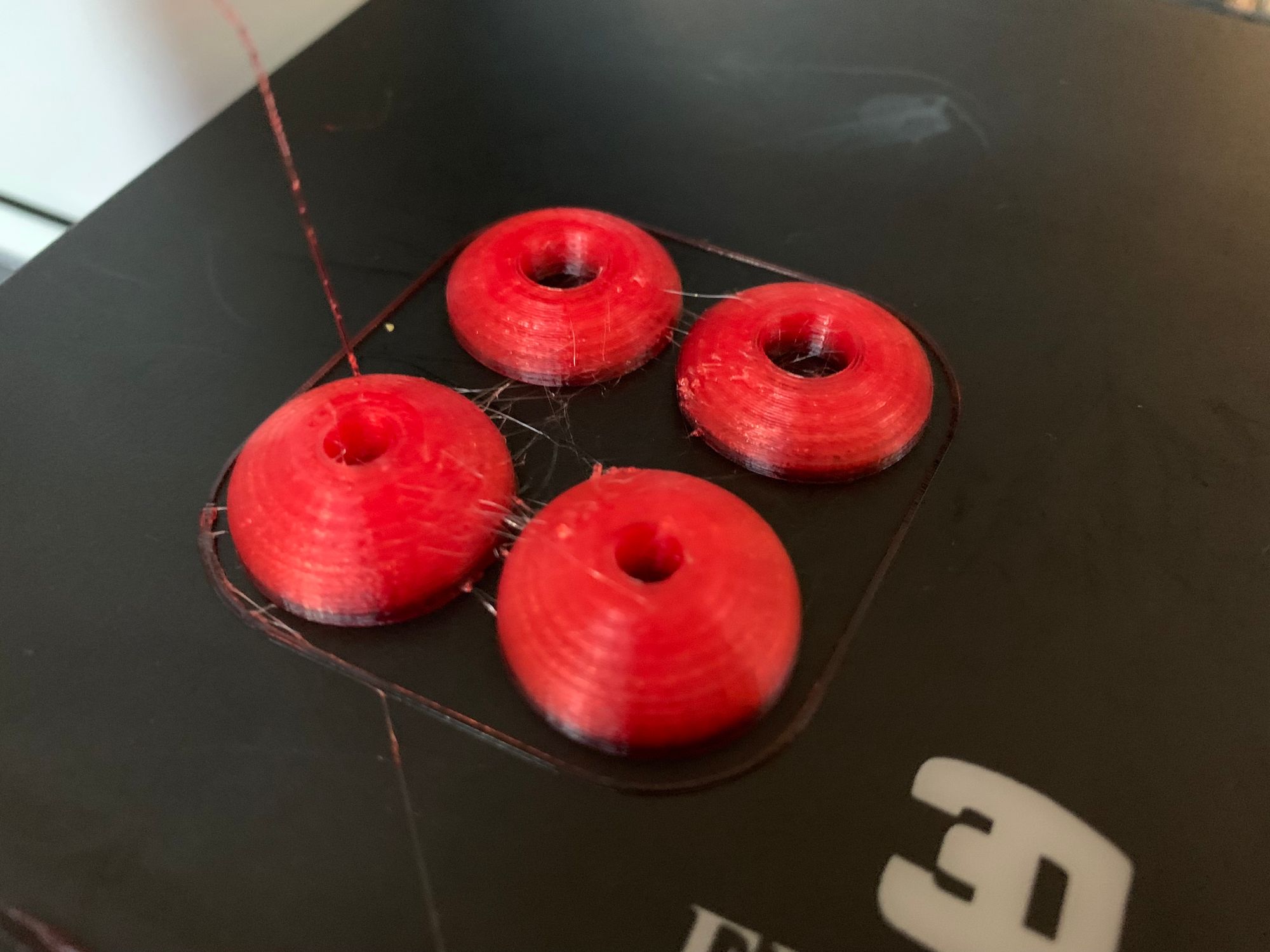
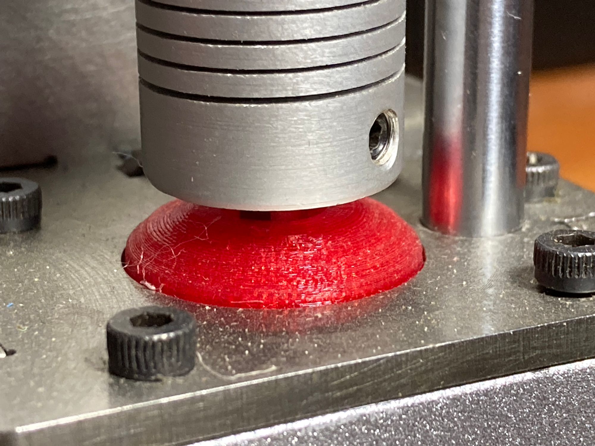
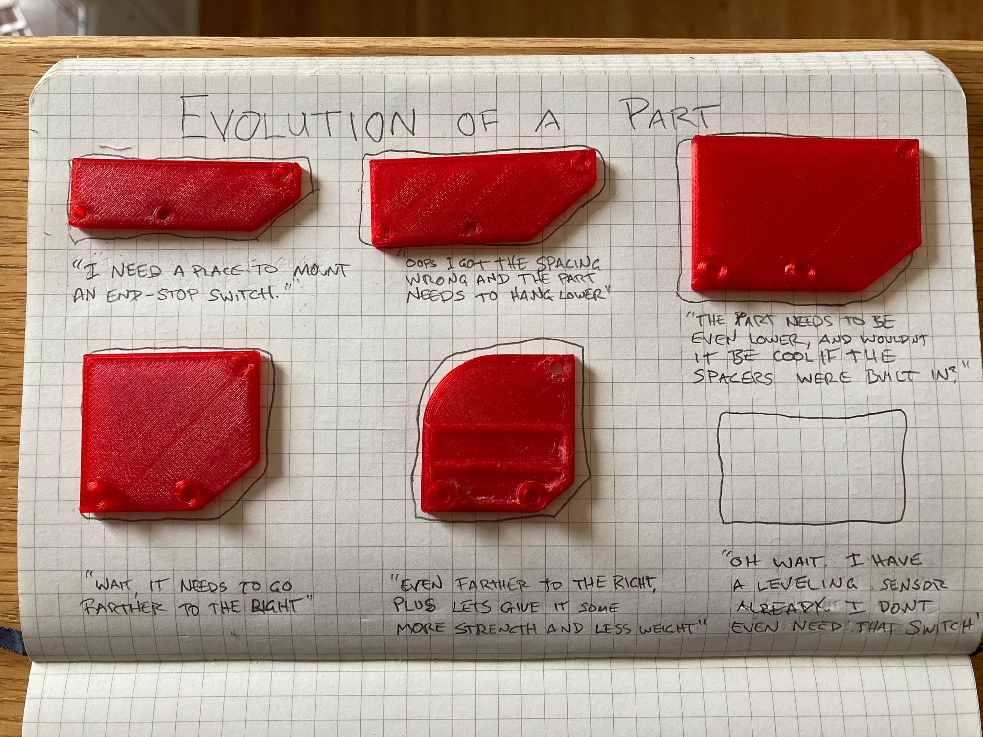
One of the parts I did design from scratch: A cap for the Z-motors. They’re purely decorative, although I guess there’s a case to be made that there might be some value in keeping dust out of the motors. Probably not, but it gave me a chance to get my feet wet in Fusion 360, and start to get the familiarity that I would need for the two parts I later did design myself.
My original plan had been to use the x-motor mount and and idler from my Alunar m505 but soon discovered three problems: first, the i3Pro Steel used threaded rods instead of lead screws. That wasn't really a problem because the threaded rod is kind of an inferior solution anyway. I had to take the lead screws from the m505. But that led to the next problem:
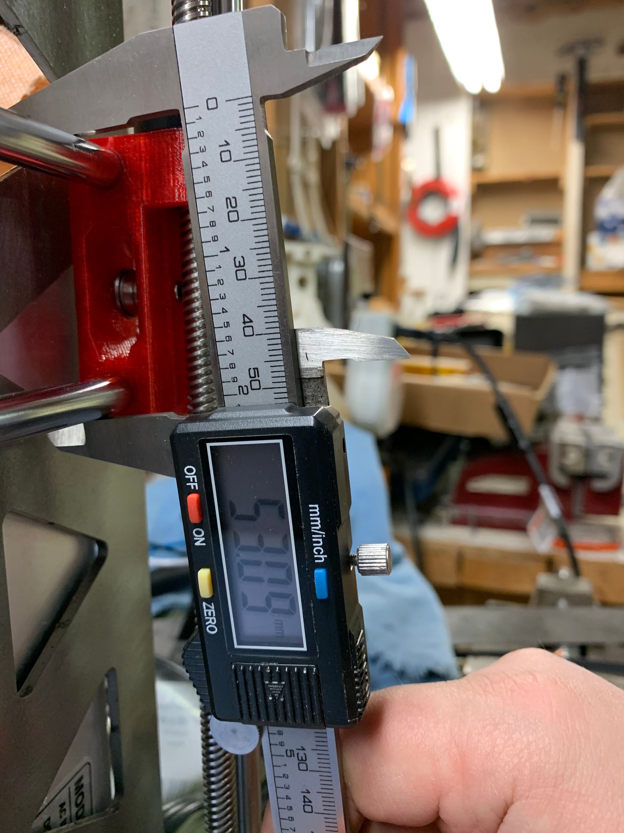
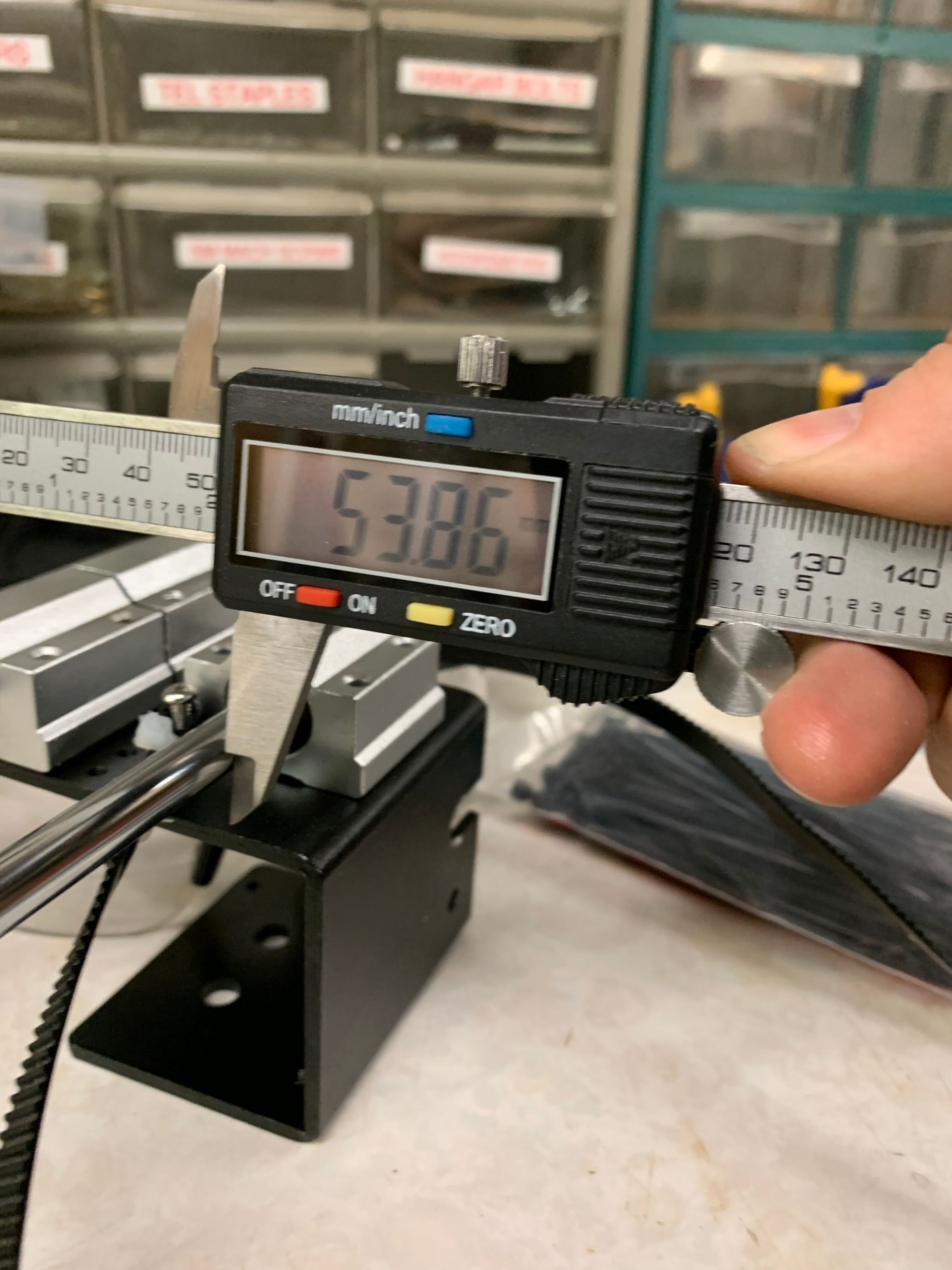
The second problem was that the frame heights of the two printers were not the same. That wasn't really a surprise but it was something I didn't know until after I compared the actual heights. After consideration and consultation I decided to buy a new set of lead screws and cut the linear rods to the correct length.
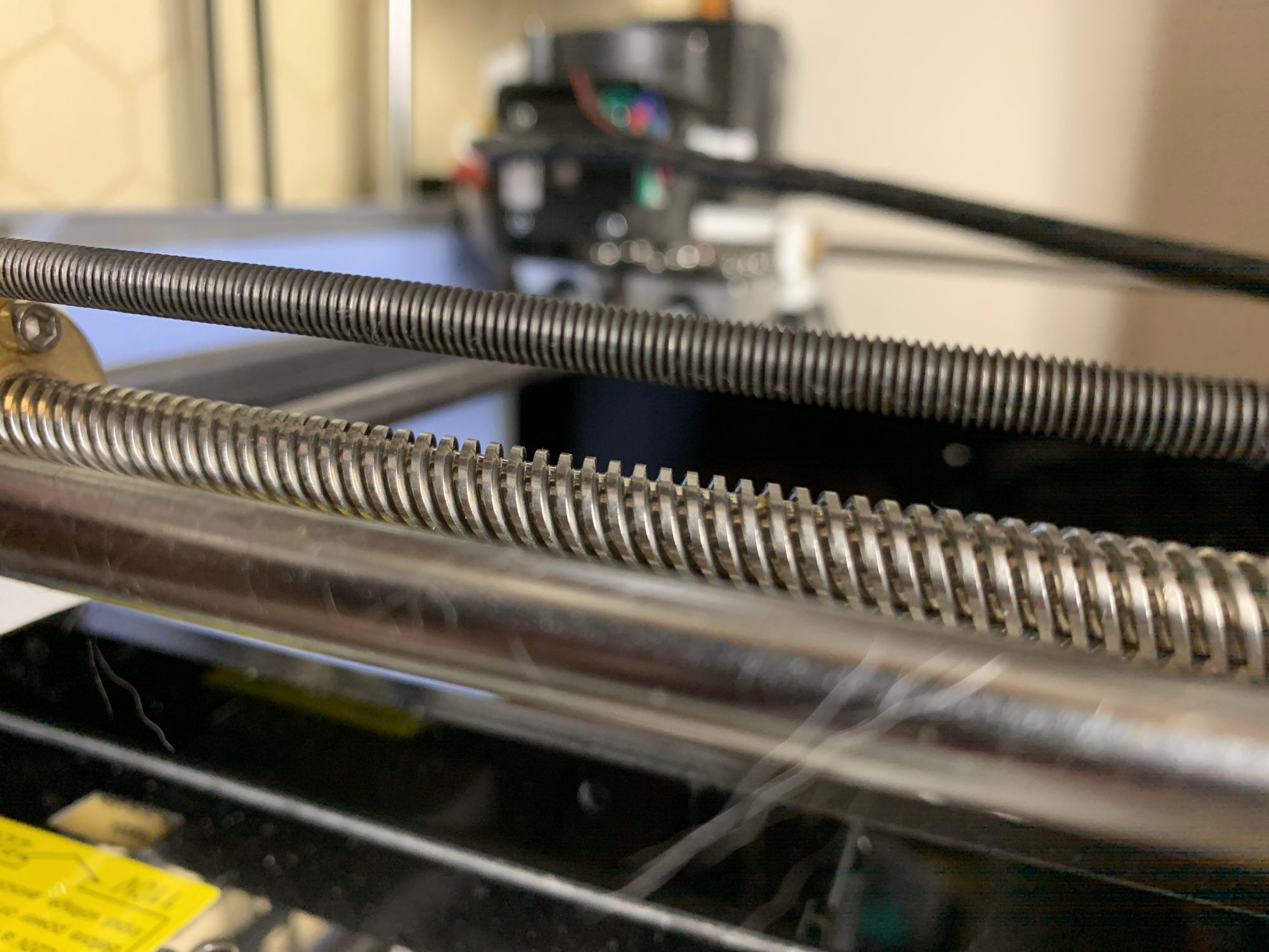
I'd never cut hardened steel before so I did a little googling before diving in with the cutoff saw. I read people talking about the difficulty of cutting it and how one ought to take it slow, have a lot of patience. The cutoff saw for metal at TVCoG is in the Welding Zone, which I’d never been cleared to use because I've never done any welding. Fortunately Dan, TVCoG’s facilities director, was willing to give me the Zone Orientation on short notice so that I could use those tools.
After all that mental buildup, preparation, and reseach it turned out that cutting through the rods took a couple of seconds each. It wasn’t difficult at all! I used the bench grinder to smooth the cut ends and I was done cutting the rods to length in just a few minutes, once I got started.
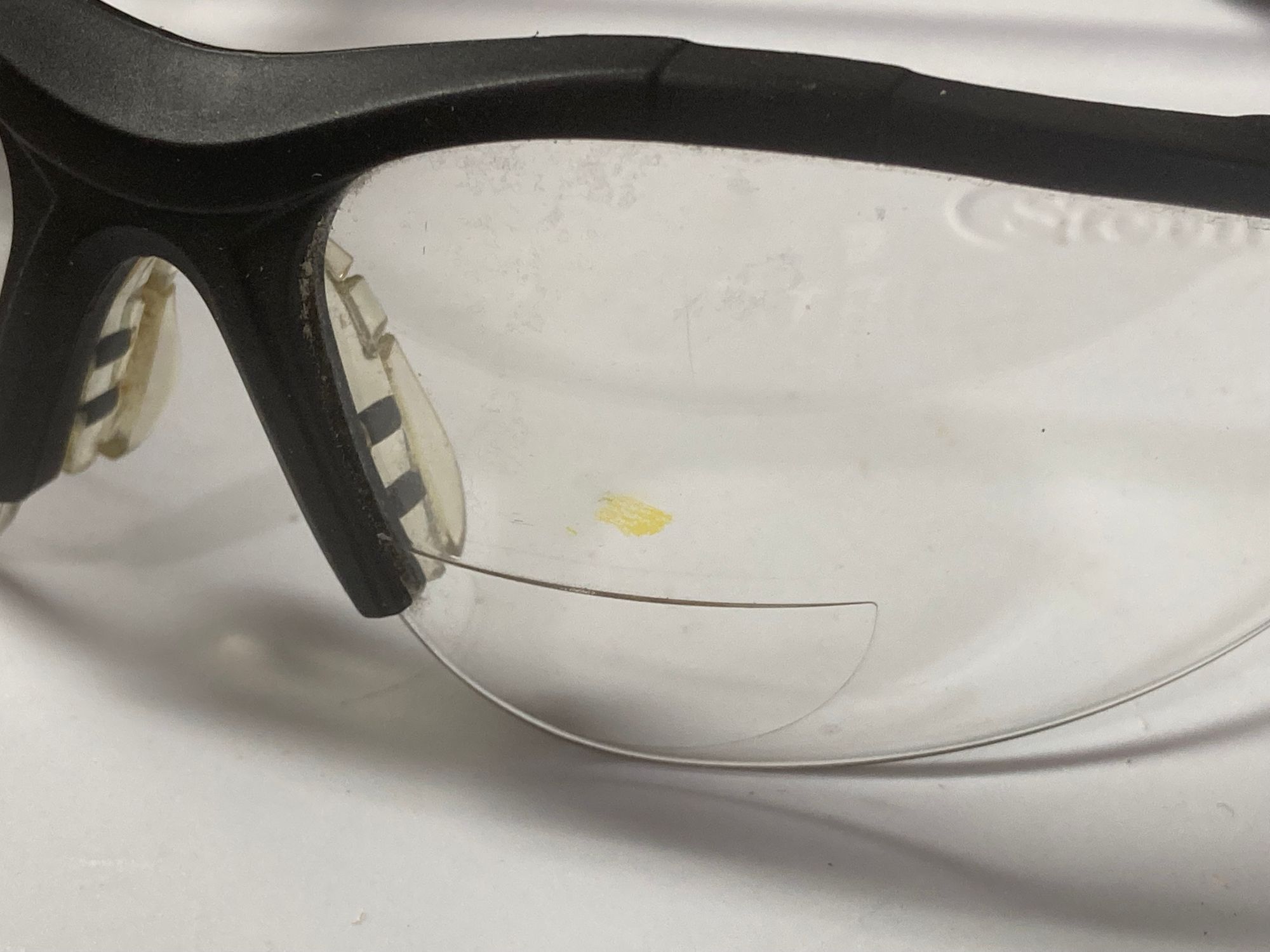
I want to note here that a spark from the cutoff saw hit me right in the safety glasses and left an amber scorch mark right where my cornea would have been if I hadn't been wearing the glasses. Just sayin’. Wear protection.
The third issue, which I had not anticipated at all, was that the that the spacing between the drive screws and the vertical linear rods didn’t match between the i3Pro Steel and the m505. Fortunately the i3Pro Steel follows the spacing for the Prusa printers, so that made it clear: that I would have to print new carriages rather than reuse the ones from my m505.
This would become a recurring theme in this project.
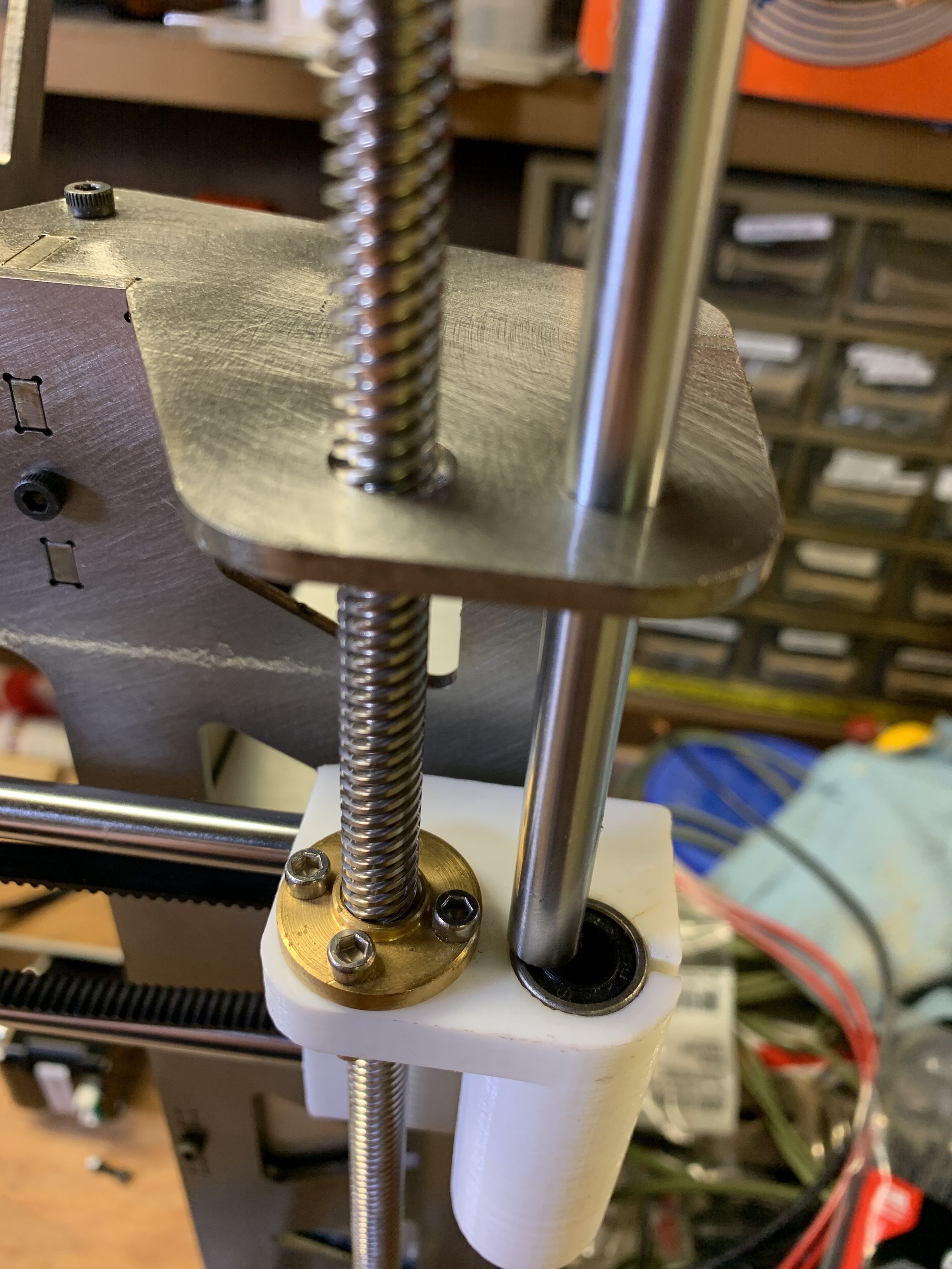
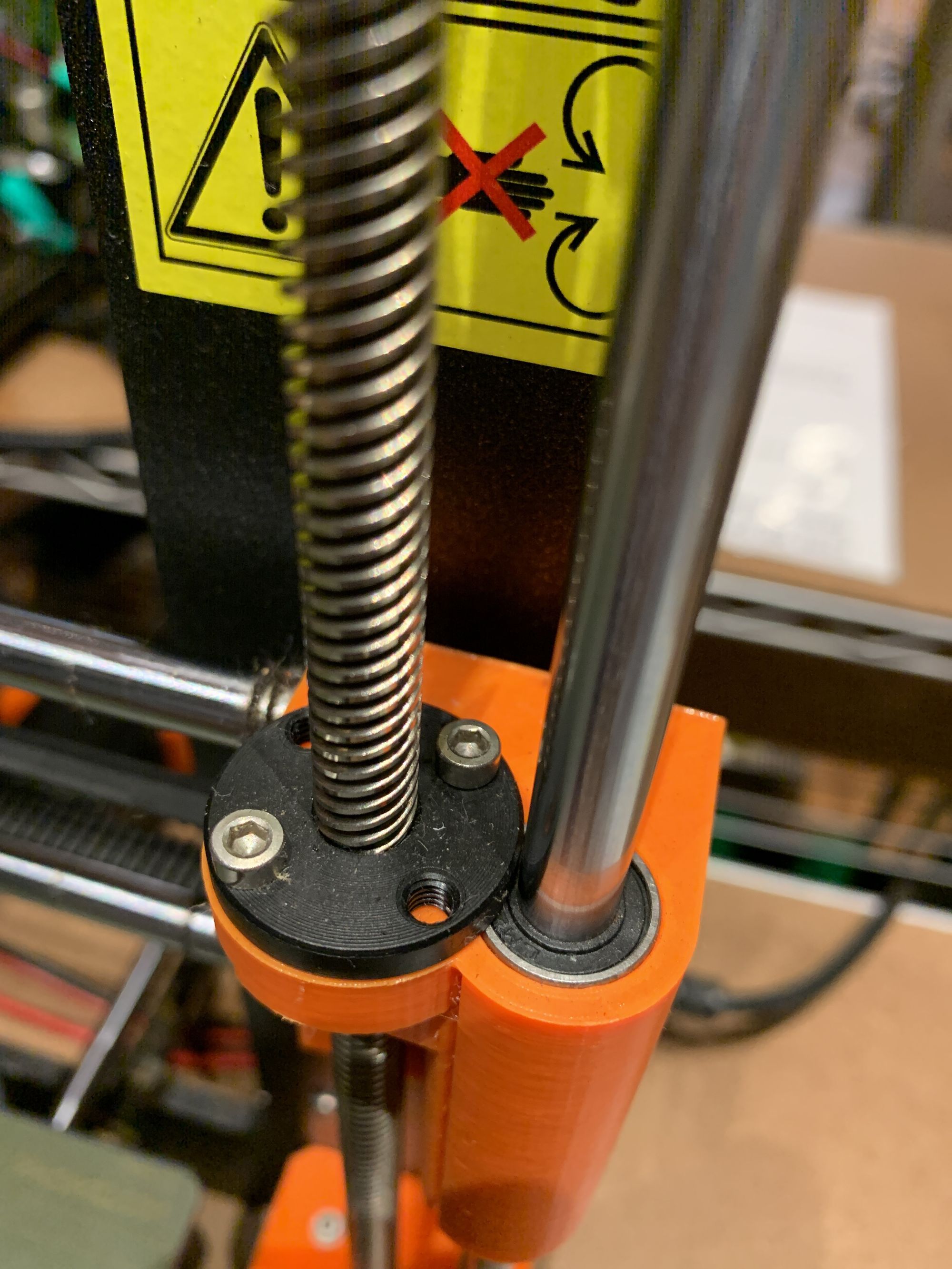
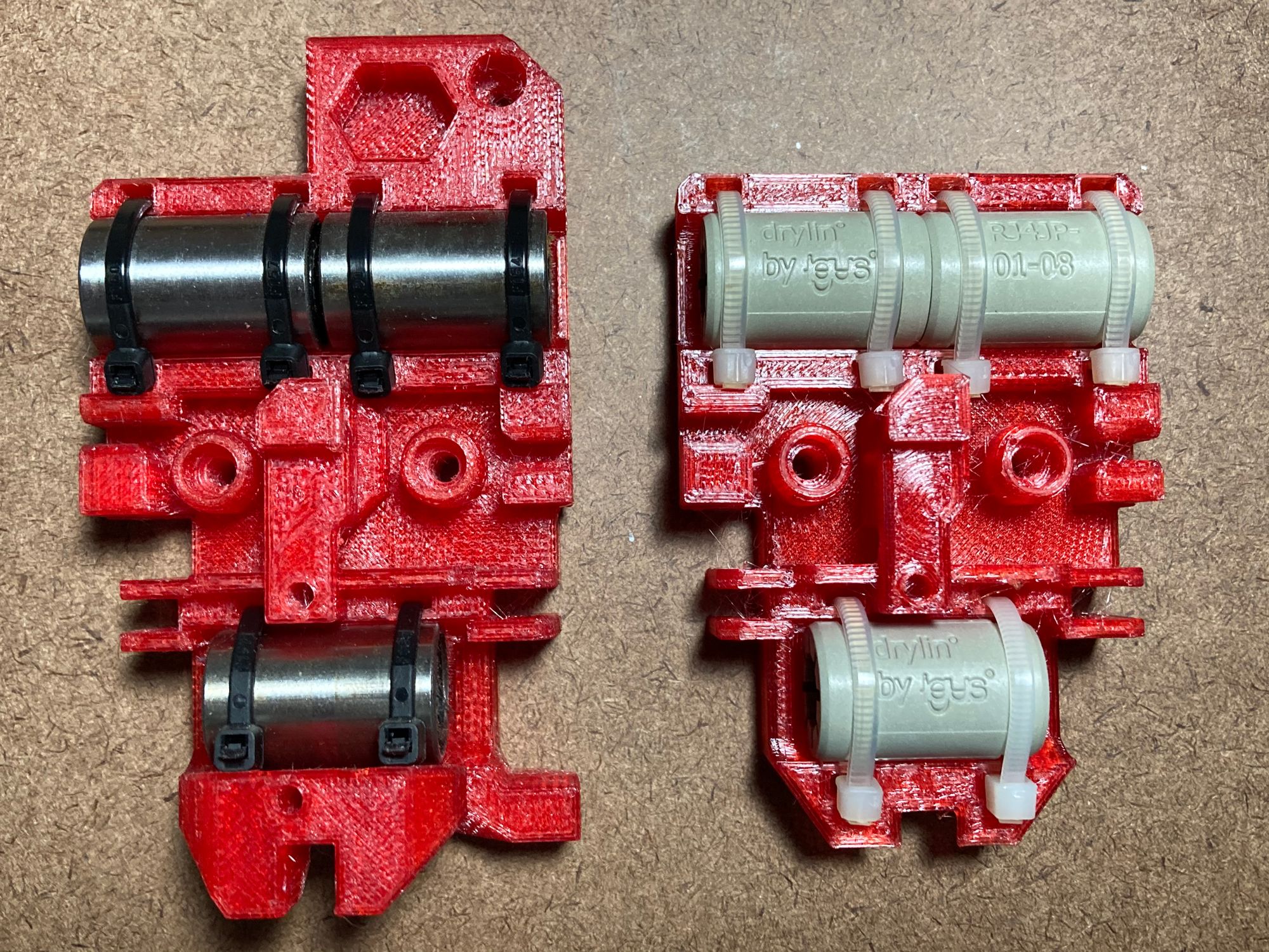
I used vekoj’s Revised X-axis models from Thingiverse instead of the stock Prusa Mk2/Mk3 X-motor and idler mounts, but only after printing a few first attempts. After I had pulled out and pushed in the vertical roller bearings a few times, the wisdom of bearing clamps instead of a straight friction fit became clear. I also wanted tensioning adjustment, which isn’t present in the stock Prusa carriage.
It’s impossible to tell this story without jumping around a little bit, because so many of the decisions I made meant going back and changing previous decisions. This should be a lesson in planning before building, but I don’t have any regrets here. This wasn’t a job on a deadline and the point was never to have the most efficient workflow. It was a learning exercise and the meandering path, while occasionally frustrating, has proven to be fulfilling.
The decision to use the Prusa motor mount and idler carriages led to the decision to print the extruder carriage. By my initial estimation, the extruder carriage from the m505 should have worked with the Prusa carriages. But first impressions aren't measurements, and nothing beats trying to put together parts that don't match for discovering that they don't actually fit.
This left me with a choice: I could edit the idler and motor mount carriages to match the spacing of the m505’s extruder carriage, or make a new extruder carriage.
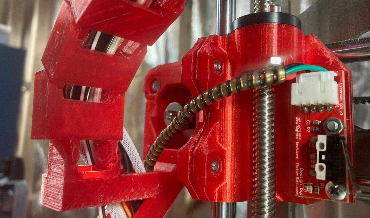
I mulled this decision for a while and ended up going with a new extruder carriage. The simplest reason is that changing one part is easier than changing two parts. I also liked the idea that I could print this part and have more in the lovely translucent red I chose for the project. I pulled a few versions of the carriage from Prusa’s download site and added and removed parts to fit my needs (more on this when I talk about the cable chain.)
I'm very pleased with my decision to use printed parts in this rebuild. I like the look of the brushed steel next to the translucent red parts, and designing (or at least modifying) new parts has been more of a learning and experimenting experience than I could have hoped for if I only rearranged preexisting parts.
There will be more about these parts later. I'm sorry to string it out so long, but I'd like to keep this account to smaller, more digestible slices. It’s certainly easier to write this way. I hope it’s going to be easier to f0llow as well. So once again, I'm leaving you with a cliffhanger.
Tune in next time…