Test platform: linear regulator versus switcher

There’s little doubt about the question of efficiency: linear regulators are less efficient than switching regulators. Though I have no doubt that someone can find an example of a very efficient linear regulator that is more efficient than a poorly-designed switching regulator, such an example would be a rare exception. There are lots of numbers to back this up — just look at the datasheets.
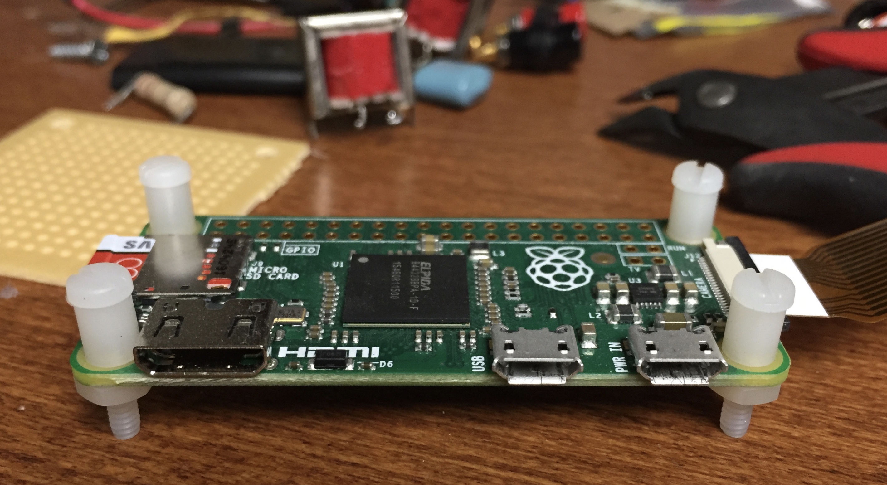
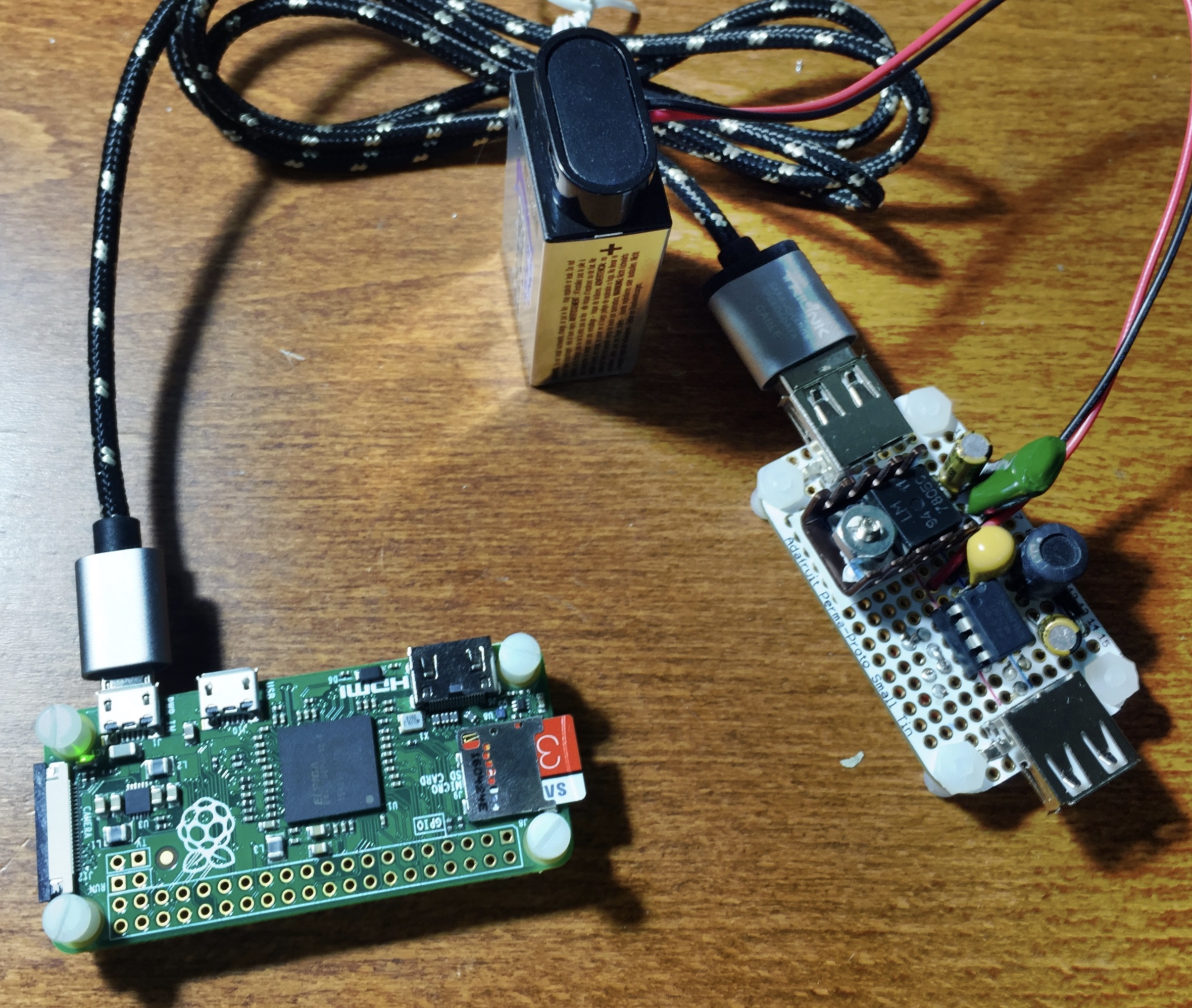
But just what do those numbers translate to in the real world? That’s what I’ve been wondering. Specifically I want to know how long I can run a Raspberry Pi from a set of batteries. I’m interested in setting up a camera to get pictures of the wildlife in the woods behind the house at night. I have the infrared Raspberry Pi camera, some Raspberry Pi Zeros, an infrared light source, and I’m trying to find the best way to power it all.
There are too many threads to list about battery power for Raspberry Pi (but here’s one) and they tend to end up with some discussion of regulators and a lot of formulæ for figuring out how long a Raspberry Pi will last under battery power. Also Jeff Geerling did a very nice series of tests of current draw for various models of Raspberry Pi.
There is a lot of information out there but these all end up being rather theoretical. Someone who wants to know how their solution will perform will have to do their own tests. This is as it ought to be: no one can anticipate all the requirements of someone else’s project. It seems nevertheless valuable to have some rough estimates of what to expect.
The few estimates I had seen were all very short — on the order of two or three hours’ runtime for a set of four AA batteries. The Raspberry Pi was not built to run on batteries, and expects five volt input. Five volt batteries are not standard, so it's necessary then to regulate the input voltage so that even if it is given more[1] than five volts, only five volts are delivered.
The cheapest and easiest way to regulate voltage is with a linear regulator, which converts excess voltage to heat. It's cheap and easy but it can be very inefficient, depending on how much voltage you're giving it. It also requires heatsinking, again depending on the voltage it's fed.
The other common way to do it is to use a switching regulator. Rather than convert excess electricity to heat, switching regulators open and close the circuit thousands of times per second using pulse width modulation to reduce the voltage. That's an oversimplification, but if you're really interested there are books you can read. The idea is that for the purposes of DC voltage there's no practical difference between 6VDC all the time and 12VDC 50% of the time, so long as you keep switching it on and off fast enough. Capacitors help smooth things out too.
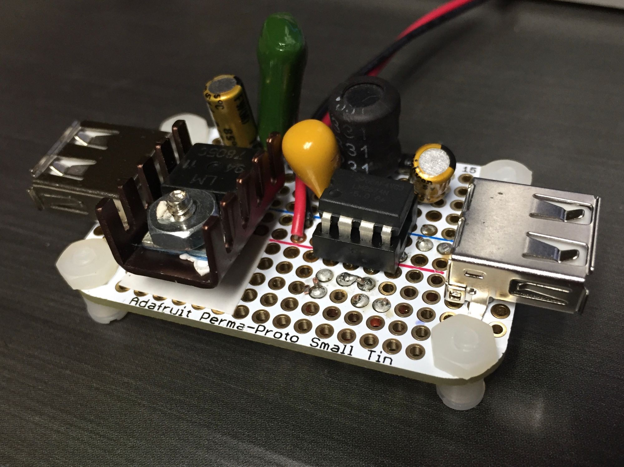
I intend to compare just how much difference there is between a linear regulator and an inexpensive switcher in a practical test with the Raspberry Pi Zero. I decided to use an LM7805C for the linear regulator and LM2574N for the switching regulator.
I built each of these regulators a couple of times with varying voltages[2] for quick tests but quickly got tired of having them take up space on my solderless breadboards where they could get knocked off the table or something. If I am to do these tests, I want one test platform all soldered together so that I can store it and reuse it, and put those solderless breadboards into service of other projects.
These are simple circuits where I haven't changed anything from the reference design in the spec sheet. The linear regulator gets an input capacitor and an output capacitor. The switching regulator needs a diode and an inductor, plus input and output caps. In order to reduce ripple while keeping the physical size low, I used a tantalum capacitor for the output cap.
What really remained to be seen was how small a card I could use and still fit both circuits, keep them nearby to one another. For a tester I don't much feel the need to have an enclosure with mounted plugs. In the end the resulting circuit will go onto a ProtoZero Board where I'll also have to conserve space. But that's not for this project.
In the end I chose the smallest perma-proto board I have, a mini-Altoids tin-sized board from Adafruit. I have a few more so my mint tin needn't go to waste.
Perma-proto boards sometimes waste a lot of space. There are tradeoffs to be made between one-hole-per-pad multi-solution boards, stripboards, and boards with the layout already built in. I generally like three-hole-per-pad board best, but the perma-proto boards that mimic solderless breadboard layouts have the obvious advantage of being able to exactly accomodate a design one has worked out on the breadboard. It might not be the most efficient, but you can get it to work and just translate it to your perma-proto. This one in particular saves considerable space by placing the power rails in the center, where a PDIP package IC can straddle. It makes a good compromise for a small space and no-brain layout.
I included one power input and dual outputs. I could run both at the same time (and technically do, but one at no load). I used USB ports because it's 5V — nothing attached to the data ports so you could charge your phone with this little card. Of course, you'd still need to find a power source but again: it wouldn't have to be a 5V source. Just something higher than 5VDC and below 40VDC. And be careful about that heatsink if you're getting up to more like 40V.
The results of the testing will be in a later post. What you thought it was going to be here? I still have a lot of AA batteries left to drain before I'm done.
Or less, of course. But generally speaking it's easier to reduce voltage than it is to step it up. ↩︎
For the switching regulator the voltage is indicated after the chip's designation number. The IC package is for the 5V regulator is LM2574N-5.0, the 12V regulator is LM2574N-12, and the adjustable is LM2574N-ADJ. The linear regulators use the last two digits of the numerical part of the part number to designate the voltage, so the 5V regulator is the LM7805 and the 12V regulator is a LM7812. The adjustable version of this is the LM317T, though all of them are actually adjustable, just with different base output voltages. ↩︎