Makerfront Rebuild Part 3: Upgrades!
When I first brought the Makerfront frame home I intended to buy only three additions to modernize the printer, naïve child that I was. Feature creep is a recurring theme in this project. The further along I got the more ambitious it became.
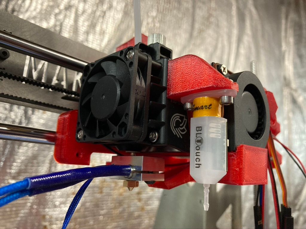
My plan (if you can call it that) was to rig the refreshed i3Pro with a new Duet 2 Maestro controller card, an E3D Hemera extruder, and a BLTouch bed leveling sensor. Everything else would be cobbled together from wherever I could scrounge, specifically my old printer and the spare parts drawers at Tech Valley Center of Gravity.
Maestro!
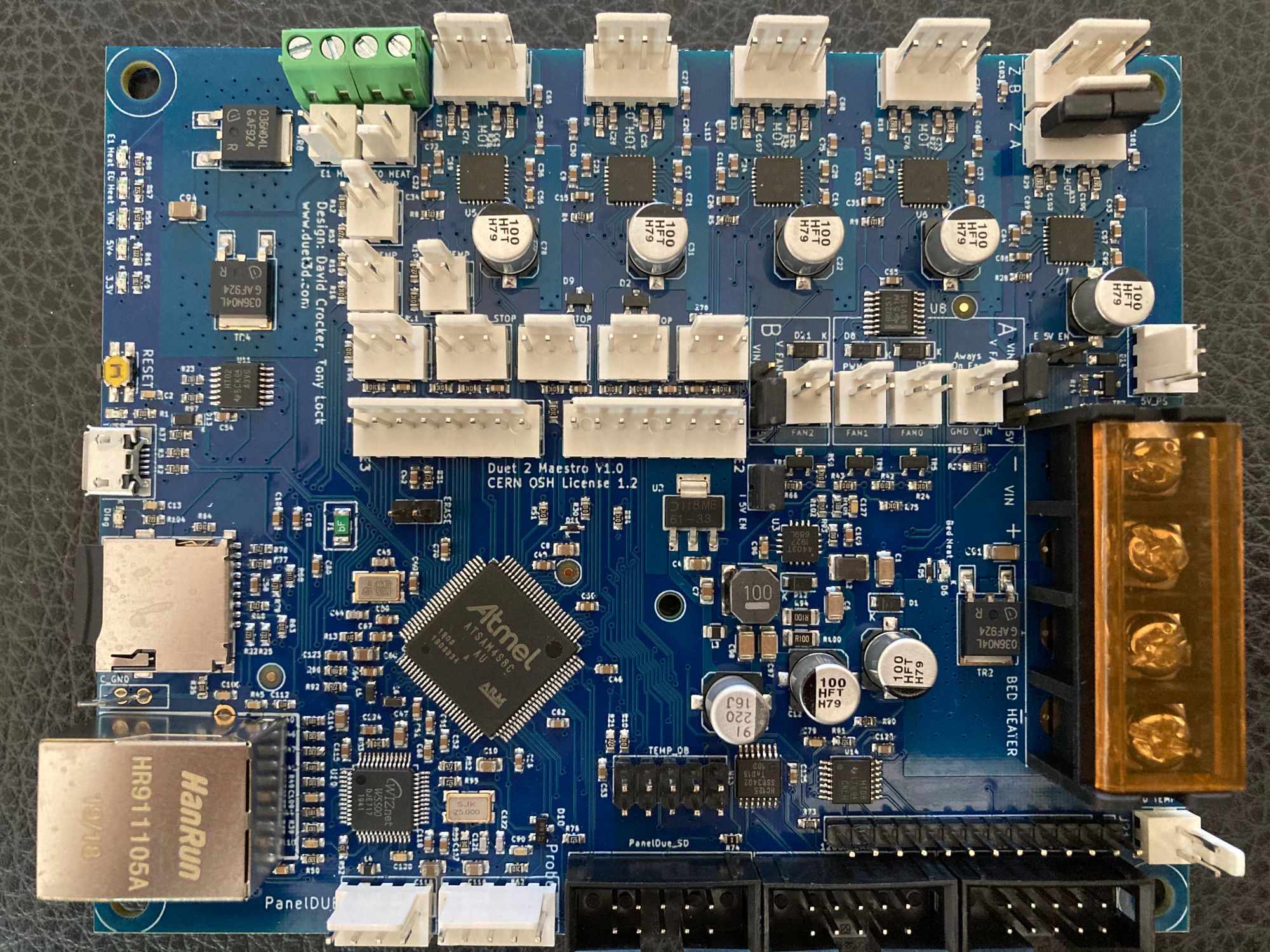
The Duet 2 Maestro card is a 32-bit controller with a lot of features compared to any of the old 8-bit cards. The Maestro is probably all one could ever need for a run-of-the-mill cartesian FDM printer. Time will make a lie out of that last statement but the (relatively) new generation of 32-bit controllers eliminates many shortcomings of the older boards. Printing can be quieter and faster as the boards calculate factors like motor speed more quickly and with more precision.
The higher-end Duet cards control more motors and sensors, making them suitable for complex CNC applications. The Maestro has enough dedicated outputs to run this style of 3D printer, has a built-in webserver for configuration and control, and is significantly less expensive than Duet3D’s higher-end boards. The most intriguing thing about the Duet controllers is that everything — including board configuration — is done with gcode, the control language used by 3D printers and other CNC devices. This means not having to recompile and upload firmware images to make configuration changes on the Duet controllers.
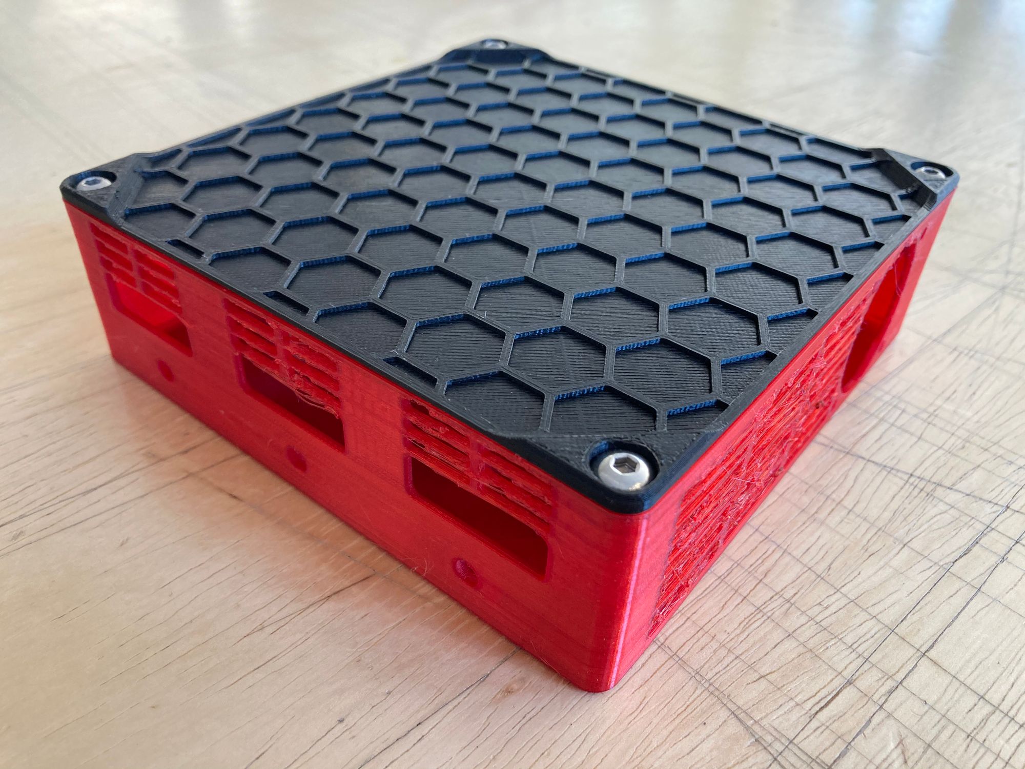
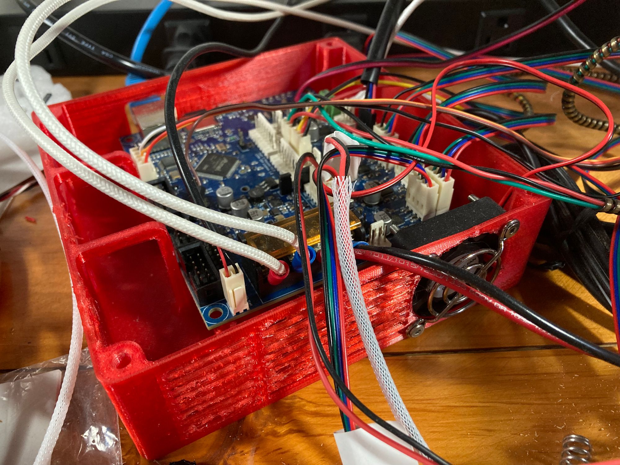
I printed an enclosure for the Maestro from Thingiverse. I might make something else later, or modify the top to accomodate the wires. But for now it keeps the controller board off the table and looks pretty good except for the mess of unmanaged wires I haven't dealt with. It has a mounting point for a cooling fan and channels that pull air from the outside right across the MOSFETs. It printed with some bridging problems, but considering that the vents were horizontal slits it’s impressive that it printed at all. If I remake it I'll edit it to use diamond or hexagonal vents.
Hermes… no wait, I mean Hemera
Hermès, the luxury fashion accessories company, threatened to sue E3D, the 3D printer parts company, over its decision to name the new extrusion system Hermes, after the Greek god. At the last minute E3D renamed the extrusion system Hemera. I ordered mine early enough that it shipped with the original Hermes sticker.
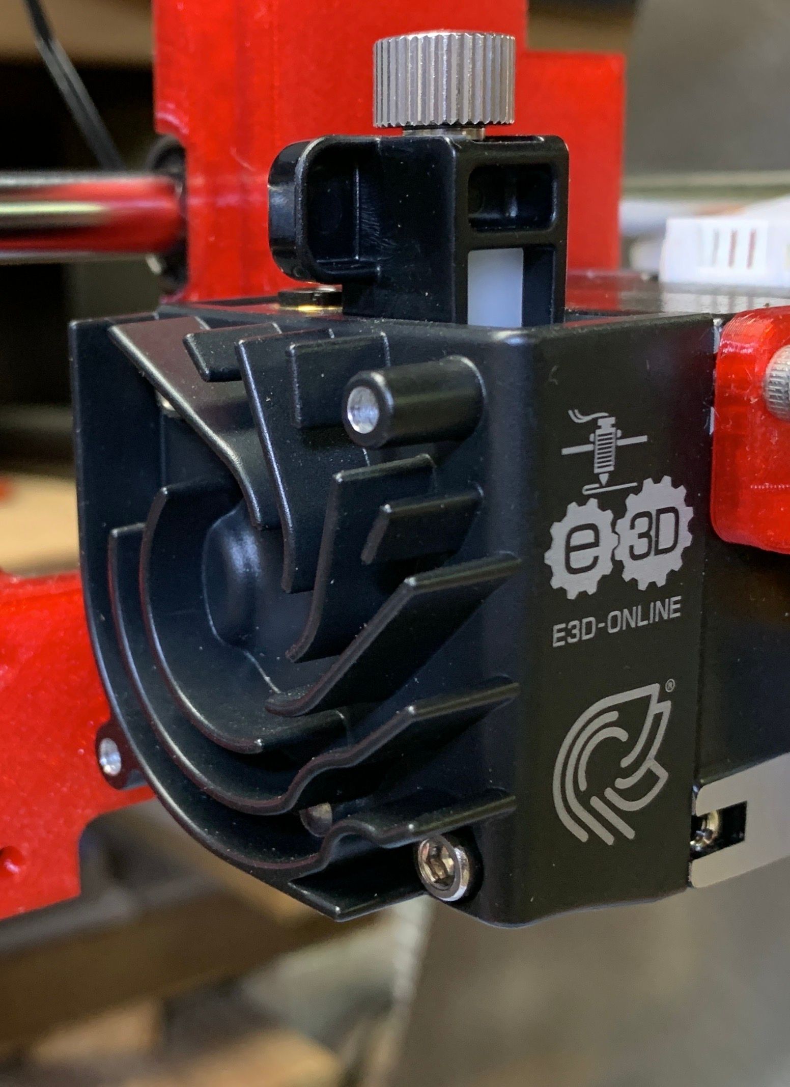
What's so special about the Hemera? I can’t say anything about it that E3D's own hype won’t tell you better. Honestly I chose it because whenever I mentioned it to people who know more about 3D printers than I do, those people always said it was awesome. So it was peer pressure, but perhaps a good kind of peer pressure.
Hemera’s signature heatsink design pushes the heated air up and away from your print, reducing breezes which might disrupt the print’s cooling. The dual-drive sharpened-steel drive train purports to keep a good grip on filament. I’ve had problems with filament stripping, so if this actually works, that’s good news. Hemera is an integrated extrusion system so installing it was straightforward. E3D also sells Hemera as a Bowden tube kit, but I decided on direct drive.
Extra Sensory
I wanted the BLTouch sensor for my older printer before I thought about rebuilding the Makerfront. Manual four-point bed leveling drives me crazy. It always seemed wrong but I couldn’t put my finger on why until I read Mark Rehorst’s post on three-point leveling. That post made it clear why it never worked very well. Thank you, Mark. By the way, I’m a huge fan of those pencil diagrams on lined paper. Screw slick graphics; those diagrams are effective.
Inspired by that post I decided I must have a three-point leveling system in addition to the sensor, reasoning that the less the autoleveling system has to correct for the better. That’s where I had to start rethinking what I was doing. I had planned to install the borosilicate bed from my m505 onto the Makerfront. But three-point leveling requires three holes in the bed and a support plate with holes to match.
I did not want to drill a hole in my heater. I also did not want to try drilling a hole in my borosilicate plate. Neither the support plate for the Makerfront nor the support plate for the m505 had holes in the right place, or even places where the new hole would have to go for three-point leveling.
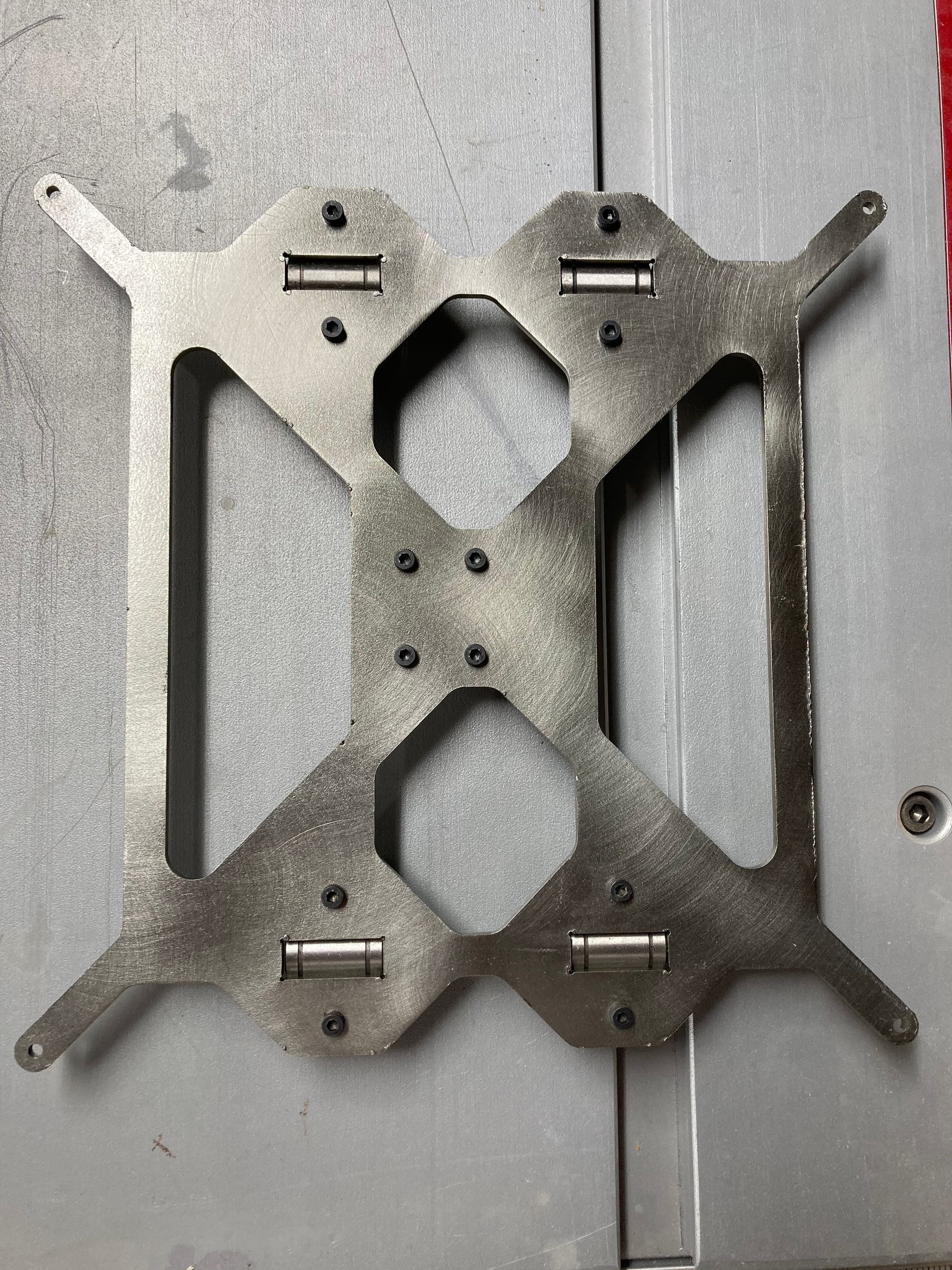
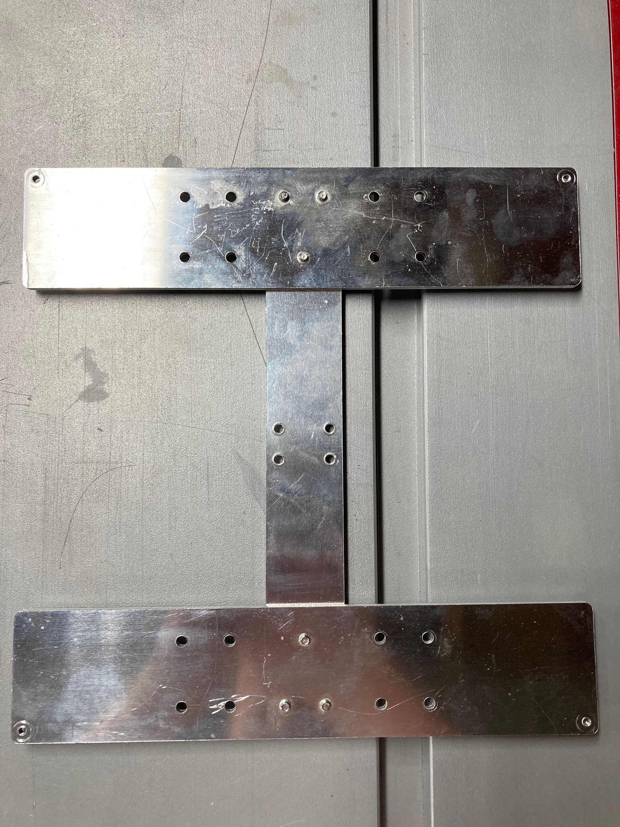
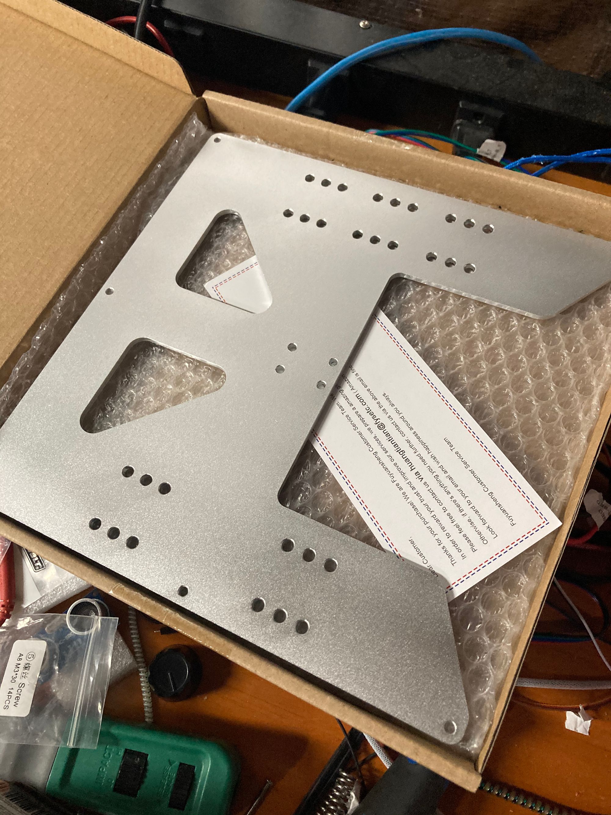
I felt bad about removing the original Makerfont support plate. It’s a lovely shape and looks gorgeous in brushed steel. Maybe I 'll hang it on the wall in my shop.
Choosing three-point leveling meant I didn’t only have to replace the support plate. I’d also have to get a new heated bed. I didn’t want to drill through PCB and risk breaking one of the traces so I had to consider other kinds of heaters.
Here comes the cascade of changes
I’ve read good things about silicone heater pads; they reportedly heat up rapidly and evenly. My new plan became to get an aluminum plate to mount the heater to, drill the holes in the right places, add some silicone spacers, and print some thumb wheels for adjustments and it would be done.
Perhaps that's what I should have done. But as I thought about getting a heater that would heat up the plate rapidly, a nagging thought started bubbling up from the back of my brain. If I really wanted to heat things up faster, wouldn’t I be better off switching from a 12 volt system to 24 volts?
I can hear you laughing from all the way over here.
Changing voltage is not just a matter of swapping out the power supply. All of the components that are connected to it have to be able to take the higher voltage. I’d already bought my extruder and my control board. And what about the motors?
Those questions were answered with mostly good news. Those NEMA 17 stepper motors have a pretty wide range of operating voltages. I bought new ones anyway. I splurged on a set of 1.5 Amp/phase 1.8 degree NEMA 17 motors with an operating voltage range from 3.6V to 36V.
The Duet 2 Maestro operates at 24V as happily as it operates at 12V. So that was no problem.
The Hemera was the question. Hemera is offered in both 12V and 24V models, which suggests that they aren’t interchangeable. That was discouraging but not disqualifying. I could get a 24V-to-12V converter, or even build one. They're inexpensive and some folks online claim to have used them this way.
Eventually I found the difference between the two models. The heater cartridges come in 12V and 24V models, and Hemeras ship with one or the other. A new E3D-branded 24V heater cartridge is $18. If I’d had to replace the $160 Hemera I'd have stuck with 12V. At $18, there was little reason not to go for 24V, save common sense. I ordered a 480 Watt 24V power supply, the 24V silicone heater cartridge, and a 3mm aluminum plate.
Wait. That was too easy
If replacing the support plate solved one problem it created another. The shape of the new plate was such that the Y-axis end stop switch mounted on the rear of the frame no longer touched the support plate. The plate went all the way back but the switch was not even close to touching. Due to a difference in the way the bearings are mounted the switch was also at the wrong height.
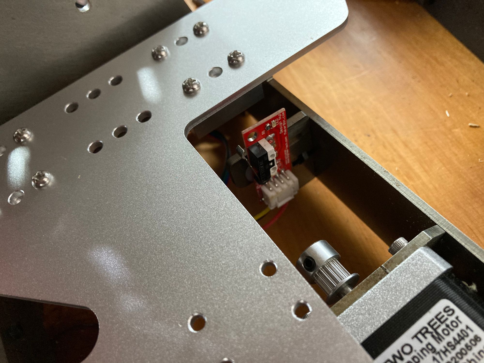
In some other design this might not have been a problem. I could have changed the position of the switch. I could have mounted it differently. I could have done something different. Without making a new piece or milling out new holes in the frame, the switch wasn’t going to work.
The easiest solution (that I could think of) was to attach something to the frame to cover that space. It would extend out and down a bit. I designed and printed a brace that would fit across the "U" of the rear of the heat bed support plate, and extend down at the point where it could meet the switch.
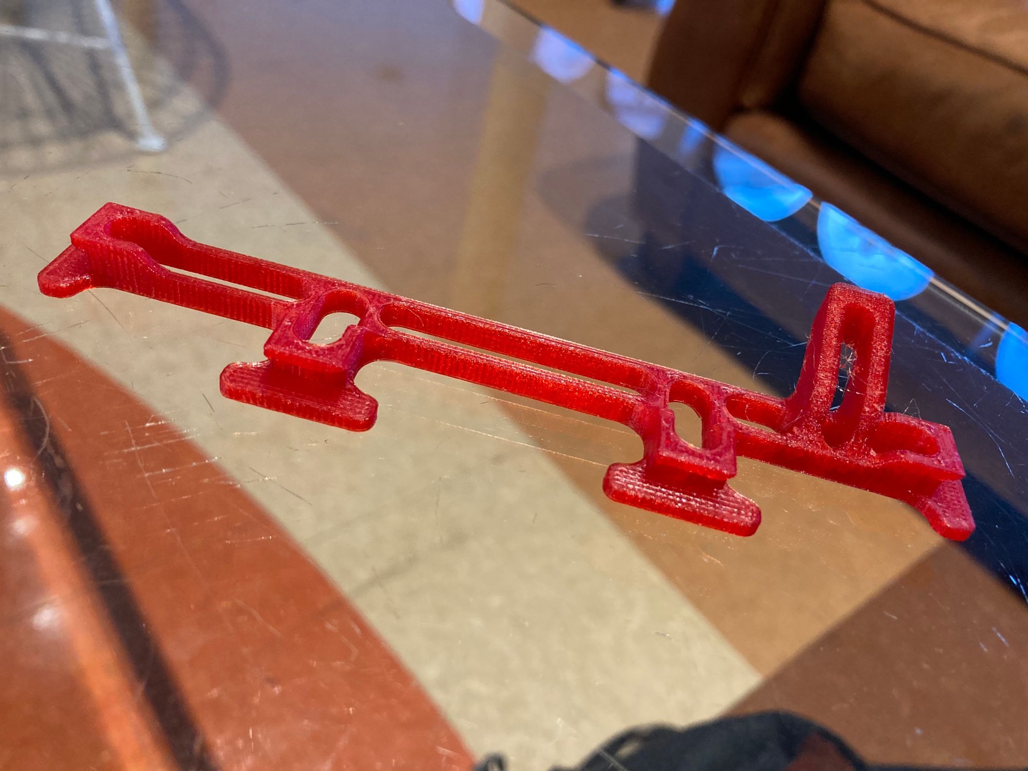
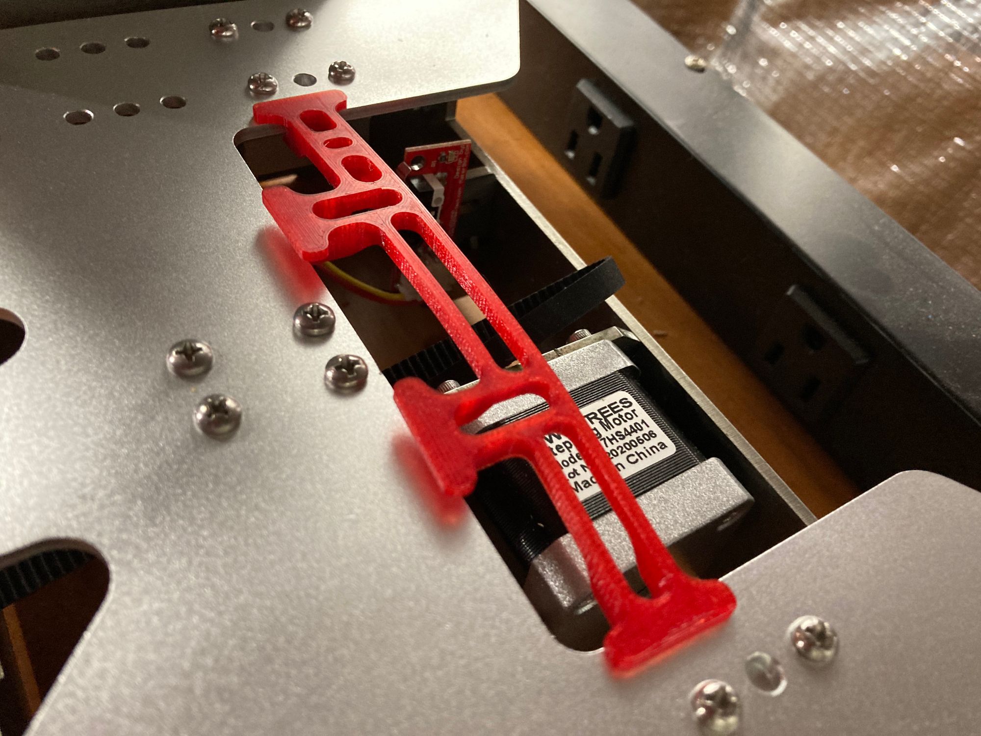
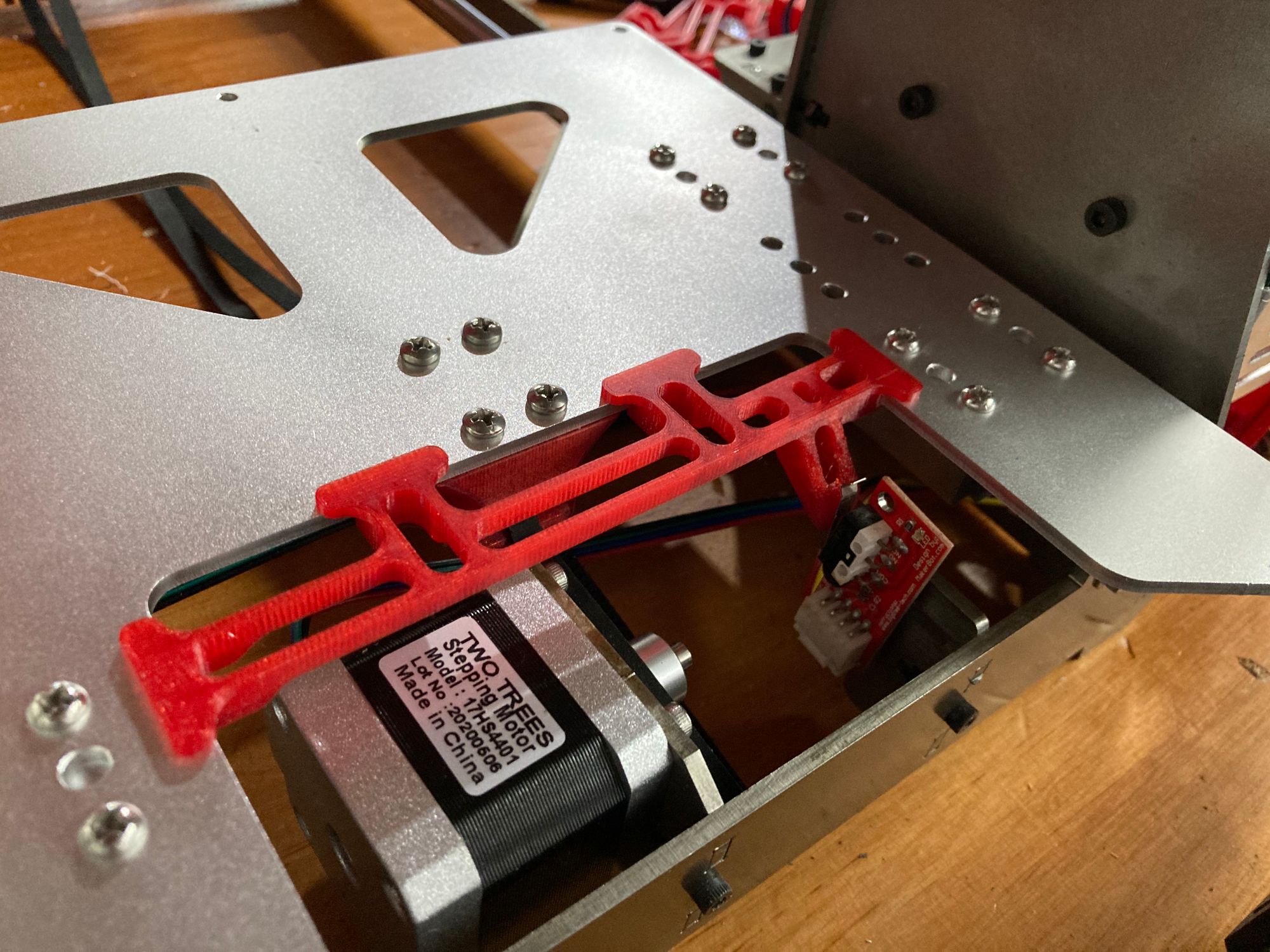
The brace attaches snugly, and touches the switch just as it should. I printed it in the same red PETG, even though it is hidden from view at all times. It just seemed right to keep the material consistent.
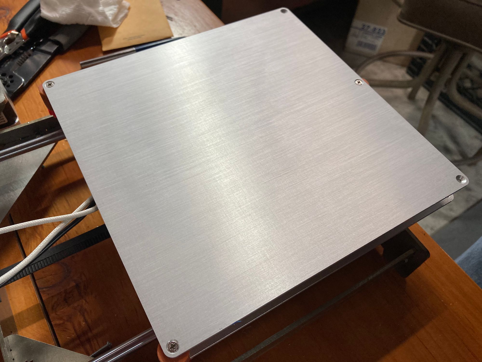
I was resigned to having a plain aluminum bed at least for a while. I covered it in blue tape and thought about maybe getting a borosilicate plate. All my spools of Overture filament come with a build surface I could attach. I thought I was happy with leaving the painter’s tape on and living with the uncertainty of a future decision to add something else. After all, I printed for a couple of years using painter’s tape before switching to borosilicate. It would work until such time as I made a decision.
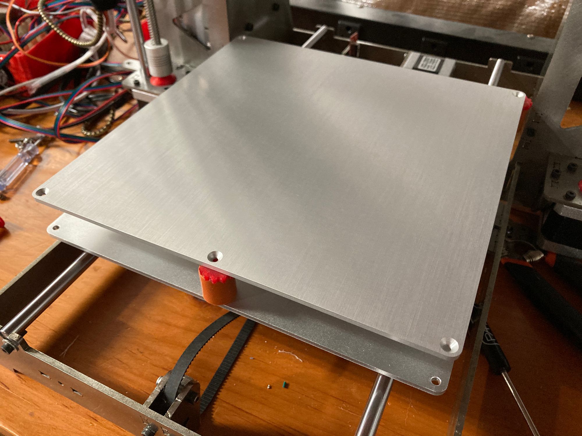
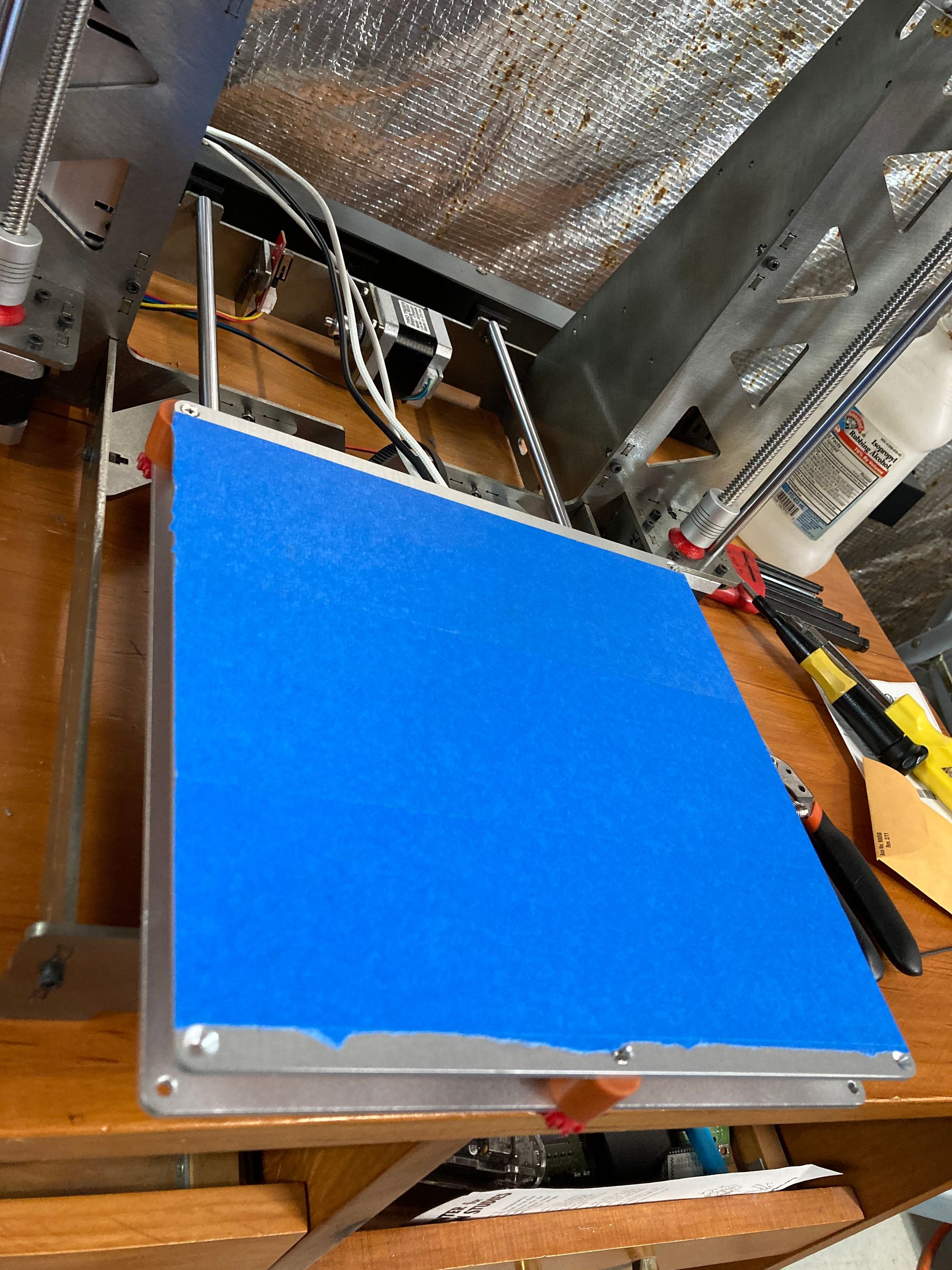
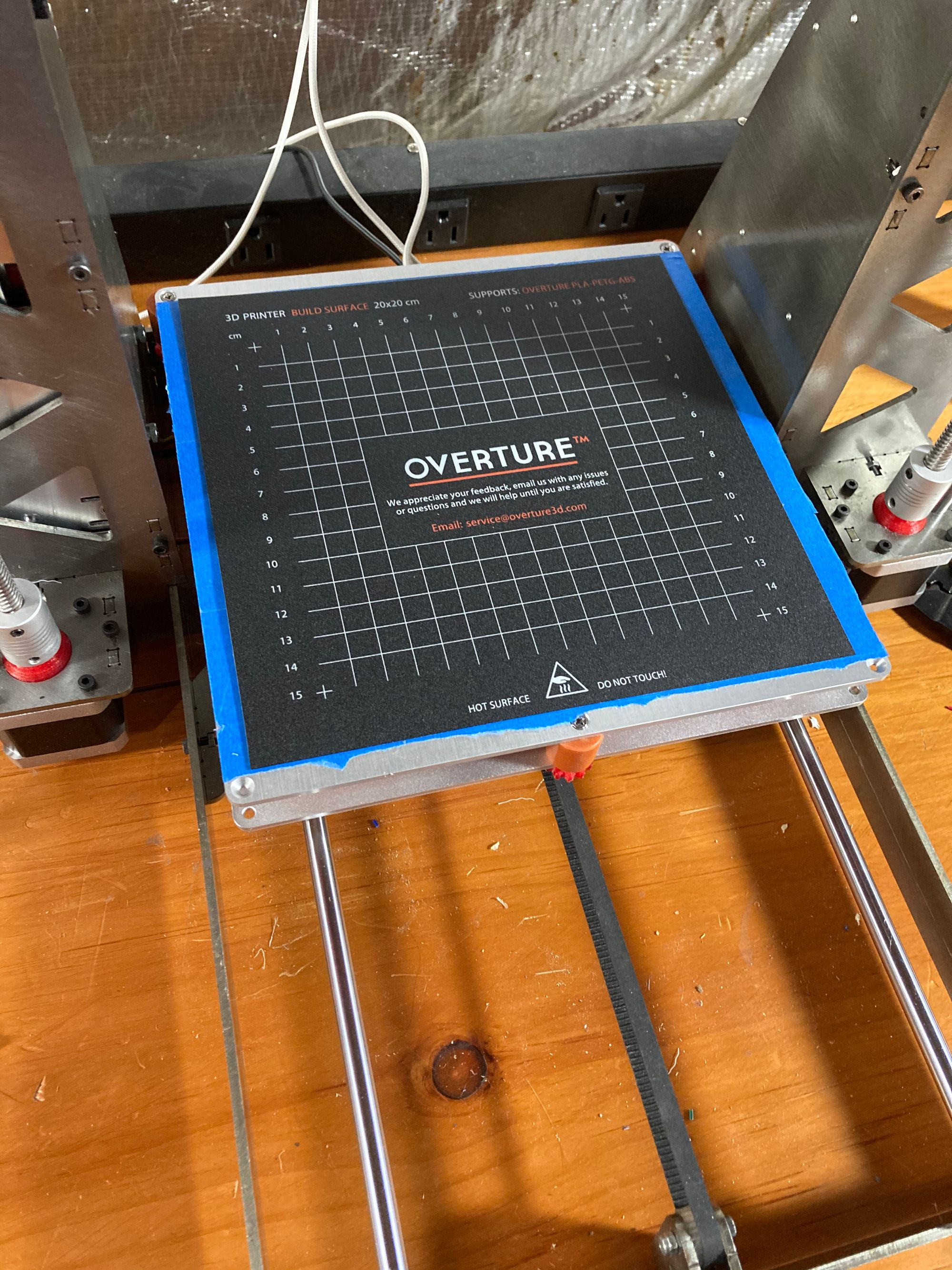
But you know me better than that. You’ve made it through two thousand words so far (more like four thousand if you read the previous two parts) and a bunch of pictures. So by now you know I couldn’t leave that be for very long.
I’ve loved the spring steel magnetic bed on the Prusas I’ve used. I can’t say they solve all bed adhesion issues, but I'll be darned if they don’t solve most of them.
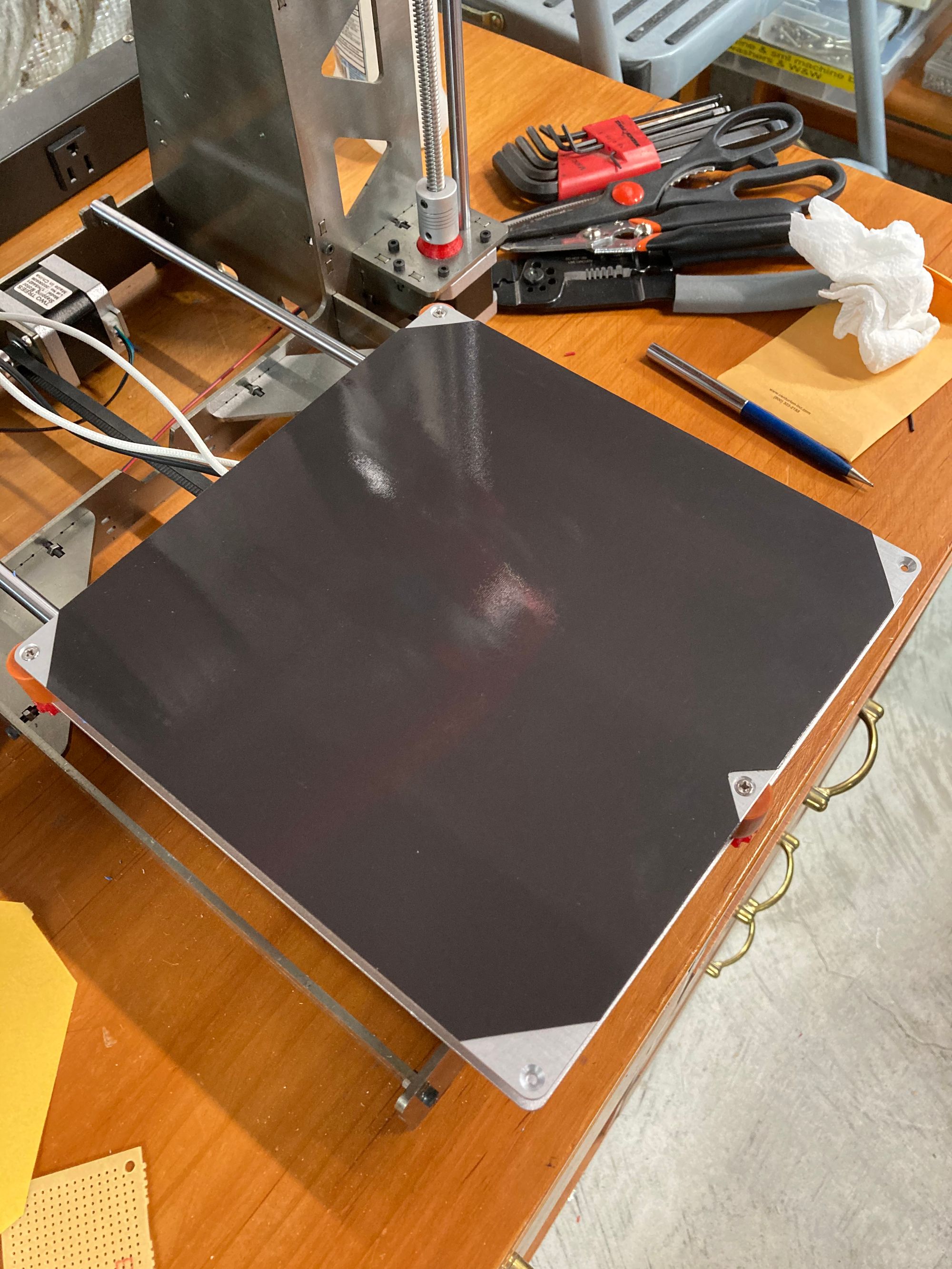
Installation was easy enough. The adhesive magnet has to go on the heatbed right, but it’s easier than installing a screen protector on an iPad. I cut out one divot where the screw for the three-point adjustment sits, and had my magnet waiting to hold its bed securely in place.
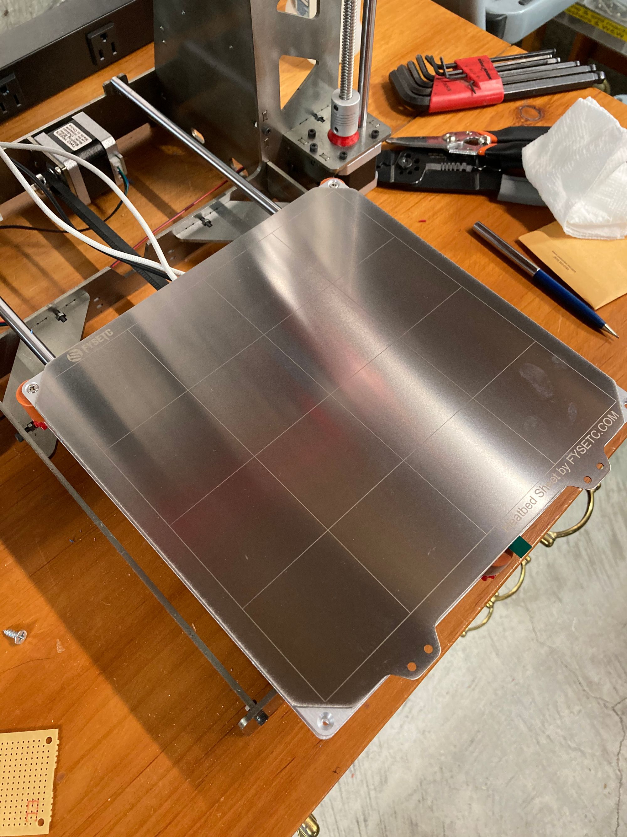
The FYSETC spring steel build surface doesn’t snap in to place like the Prusas’ do because there aren't any guide pins to align them with. But that’s a minor enough inconvenience that even I don’t care. At least for now.
That might seem to be the end of the story. Chronologically it is the end because I have skipped around in time a bit in order to keep the steps I've described related and somewhat organized. So there are more specifics I have to add in the next part, which I'll start writing soon.
