Raspberry regulator run-off
Ever since I got my first Raspberry Pi (and before; I never did anything with battery-powered applications for the Beaglebone but I certainly had some in mind) I've been thinking about putting them out in the world.

Happy Pi Day everyone!
Ever since I got my first Raspberry Pi (and before; I never did anything with battery-powered applications for the Beaglebone but I certainly had some in mind) I've been thinking about putting them out in the world. A Pi Zero-based wildlife camera is in the making here as well as other kinds of sensor-tracking items that won't go near a power outlet.
The obvious concern is how to run one's Pi from batteries. Off the shelf batteries like AAs don't come in a 5V variety. What to do?
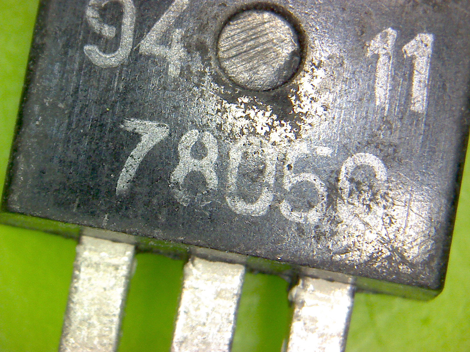
The first answer to come up when I started asking around was to use a linear regulator like a LM7805. This would take an input of a voltage higher than five volts and output a nice steady 5V. The regulators are cheap, easy to find, don't require a lot of extra components, and are a very simple, time-tested solution.
The more I looked into it, the less it seemed like a good idea. Linear regulators are inefficient; they are more inefficient the higher the voltage you supply. They bleed off the excess voltage as heat and will therefore run down batteries faster in the process of regulating the output to the voltage needed.
But this solution was proferred so often that I wondered just how inefficient the linear regulators actually are. Are people actually out there running Raspberry Pi computers from battery packs regulated by LM7805s?
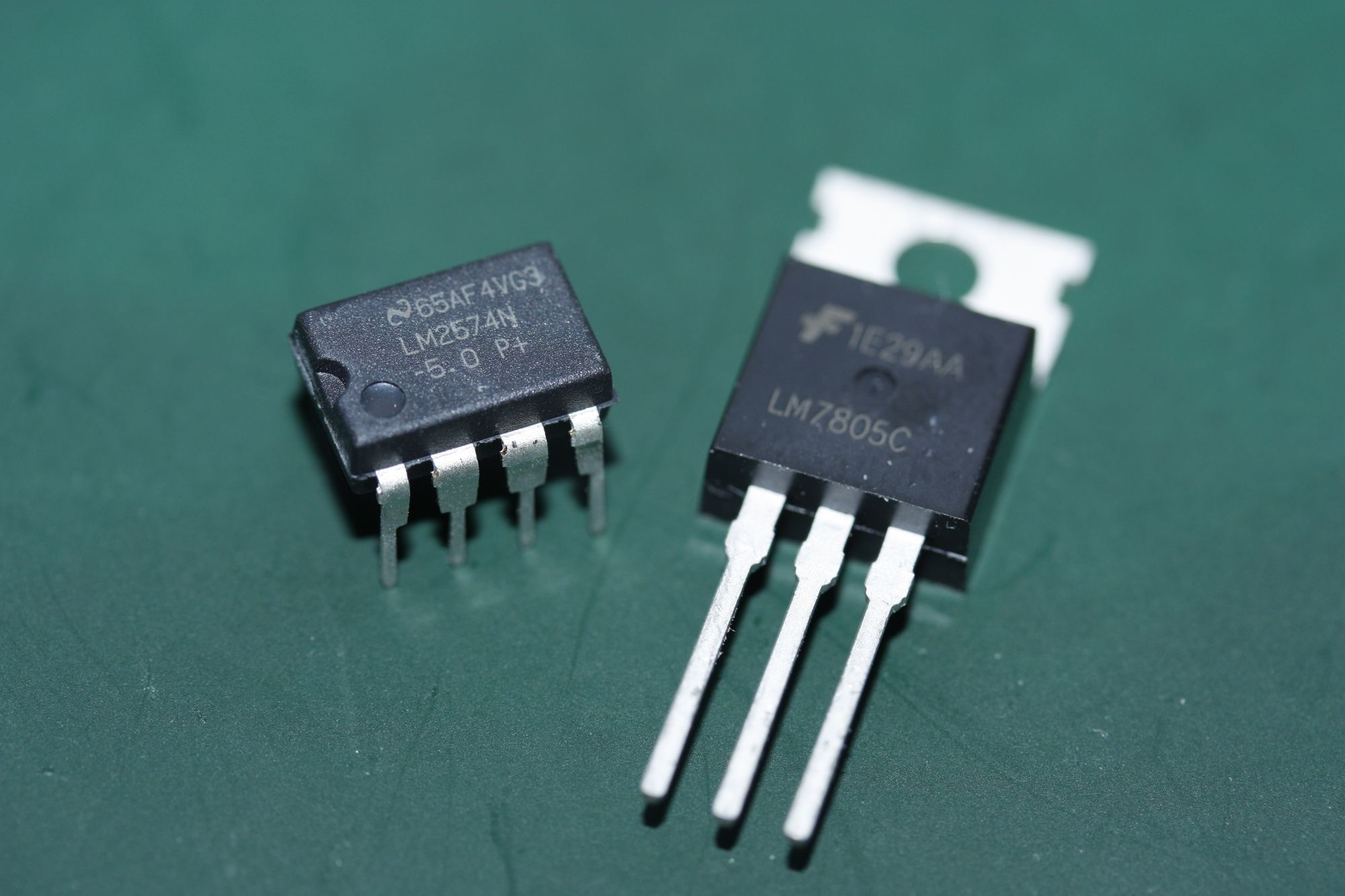
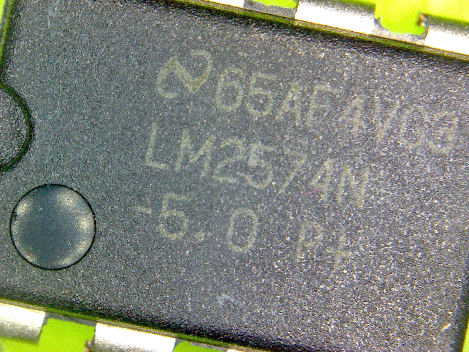
This is why I built the test platform (described in this earlier post) comprised of one linear regulator (LM7805C) and one switching regulator (LM2574). It's a very simple pair of circuits that anyone can build based on the reference schematics in the datasheets. Only a few additional components are required. Both regulator ICs are suited for low-power applications but not adequate for powering a more powerful microcomputer like a Raspberry Pi 3. I plan to expand these tests with higher-current devices and higher-capacity regulators and will report on the performance at some point in the future.
The tests
The Raspberry Pi Zero was tested in two configurations: in all cases the Pi Camera was attached (but not activated) and HDMI was disabled. This resulted in a current load of about 83-85mA with no other devices attached. During the boot-up sequence the peak current load was 175mA.
The Pi Zero was also tested with a non-powered USB hub connected with four devices: mouse, keyboard, microscope (with LED illumination) and a USB memory stick. Startup peak load in this configuration was 427mA during setup tests, and the system ran steadily drawing about 275mA.
There was an earlier attempt made with a USB Ethernet adapter connected, but the LM2574 version never booted. Meter read a load of 480mA when hotplugging the adapter after the Pi Zero was already booted, so it seems clear that the when attempting to boot with the adapter plugged in that the load exceeded the maximum the LM2574 can deliver, preventing boot. Because the Raspberry Pi Zero attached to the LM2574 didn't boot, the LM7805 was not tested in this configuration either.
The battery packs used are listed with nominal values. The 6.0V battery packs used four alkaline AA batteries. 7.2V and 9.6V battery packs used NiMH rechargeable batteries in quantities of six and eight respectively.
The results
| Model | Supply | Load | Peak | LM7805 (Linear) | LM2574 (Switcher) |
|---|---|---|---|---|---|
| Zero | 6.0V | 85mA | 175mA | 15:59:36 |
20:59:38 |
| Zero | 6.0V | 275mA | 427mA | ❌ no boot ❌ | 5:52:34 |
| Zero | 7.2V | 275mA | 427mA | 3:45:50 |
9:27:37 |
| Zero | 9.6V | 275mA | 427mA | 🔥 too hot! 🔥 | 12:17:36 |
At minimal load, the 6V battery pack ran long enough to leave a wildlife camera overnight. However, it's not clear that that's enough current to actually take images and save them to the SD card repeatedly. After the first round of tests, I went right to the higher loads without using larger battery packs.
The Raspberry Pi Zero would not boot using the LM7805 and a 6.0V battery pack under the higher load. This was not a surprise considering the LM7805 has a dropout value of 2V and therefore a nominal minimum input voltage of 7.0V. The surprise was that the Zero booted at all given only six volts. Apparently the LM7805's dropout value is dependent on the current drawn.
Under the higher loads the duration the battery packs lasted was of course much lower. That's unsurprising, but the result was such that under this kind of load there really isn't enough power to run the Pi Zero all day. Using six or eight AA batteries one could power a device overnight, but not much more.
The LM7805 with the eight AA battery pack gave off too much heat to be considered. The attached heatsink was hot to the touch. It didn't burn my skin but it was too hot to keep touching for more than two seconds. It might not have been too hot to continue running, but I stopped the experiment after only about fifteen minutes. Even if it wouldn't generate enough heat to damage anything, any outdoor application would have to be inside an enclosure which would prevent airflow and heat up anything else inside the enclosure. I don't have any measurement of the heat radiated by the heatsink, but in my judgment the LM7805 was too hot to use with a 9.6V supply.
Generally then, it seems as though a linear regulator really isn't ideal for stepping down the voltage of battery-powered microcomputers. Battery life will of course always be limited, but the aim should be higher efficiency and a wider range of possible input voltages. Even an inexpensive switching regulator performed nicely for these low-current applications.